Showing posts with label Networking. Show all posts

How to setup LACP bonding interface on CentOS 7

Introduction
A bonding network interface could be used for redundancy or higher speed requirements than 1 NIC can offer. This tutorial will help you setup a LACP (IEEE 802.3ad) bonding network interface. It requires that the switch your server is connected to is setup accordingly. If you're unsure please contact our support team.

How to setup LACP bonding interface on CentOS 7

Step 1) Login with SSH
Login as root.

Step 2) Disable NetworkManager
In our experience NetworkManager is pretty unpredictable and near useless within a server environment and we prefer to disable NetworkManager. These instructions won't work if NetworkManager is enabled!
systemctl stop NetworkManager
systemctl disable NetworkManager
Step 3) Configure nameservers
Because NetworkManager is now disabled you need to setup your nameservers manually. Open /etc/resolv.conf with your favourite text-editor:
nano /etc/resolv.conf
The content of that file should be as follows:
nameserver 8.8.8.8
nameserver 4.4.4.4
Step 4) Load bonding kernel module
modprobe bonding
Step 5) Create bonding interface configuration file
Create a new configuration file called ifcfg-bond0 in the directory /etc/sysconfig/network-scripts. We use our favourite text-editor nano to do so:
nano /etc/sysconfig/network-scripts/ifcfg-bond0
We will give this file the following content:
DEVICE=bond0
Type=Bond
NAME=bond0
BONDING_MASTER=yes
BOOTPROTO=none
ONBOOT=yes
IPADDR=89.207.131.xx
PREFIX=24
GATEWAY=89.207.131.1
BONDING_OPTS="mode=4 miimon=100 lacp_rate=1"
Please replace the IP address on the line IPADDR=89.207.131.xx with the main IP address of your server and GATEWAY=89.207.131.1 with the gateway which is correct for your IP address.

Step 6) Update physical interface configuration files
It's time to update the physical interface configuration files. Our server uses enp6s0 and enp7s0 as interfaces, so we start with enp6s0:
nano /etc/sysconfig/network-scripts/ifcfg-enp6s0
The content of this file is:
DEVICE=enp6s0
TYPE=Ethernet
BOOTPROTO=none
ONBOOT=yes
NM_CONTROLLED=no
IPV6INIT=no
MASTER=bond0
SLAVE=yes
We update enp7s0 next:
nano /etc/sysconfig/network-scripts/ifcfg-enp7s0
The content of this file is:
DEVICE=enp7s0
TYPE=Ethernet
BOOTPROTO=none
ONBOOT=yes
NM_CONTROLLED=no
IPV6INIT=no
MASTER=bond0
SLAVE=yes
Step 7) Reboot
Reboot your server with:
reboot
Step 8) Check bonding interface status
After reboot your server should have bonding active. Check with:
cat /proc/net/bonding/bond0
Output should be something like:
Ethernet Channel Bonding Driver: v3.7.1 (April 27, 2011)

Bonding Mode: IEEE 802.3ad Dynamic link aggregation
Transmit Hash Policy: layer2 (0)
MII Status: up
MII Polling Interval (ms): 100
Up Delay (ms): 0
Down Delay (ms): 0

802.3ad info
LACP rate: fast
Min links: 0
Aggregator selection policy (ad_select): stable
System priority: 65535
System MAC address: 00:25:90:XX:XX:XX
Active Aggregator Info:
    Aggregator ID: 2
    Number of ports: 2
    Actor Key: 9
    Partner Key: 20002
    Partner Mac Address: cc:4e:24:XX:XX:XX

Slave Interface: enp6s0
MII Status: up
Speed: 1000 Mbps
Duplex: full
Link Failure Count: 0
Permanent HW addr: 00:25:90:XX:XX:XX
Slave queue ID: 0
Aggregator ID: 2
Actor Churn State: none
Partner Churn State: none
Actor Churned Count: 0
Partner Churned Count: 0
details actor lacp pdu:
    system priority: 65535
    system mac address: 00:25:90:XX:XX:XX
    port key: 9
    port priority: 255
    port number: 1
    port state: 63
details partner lacp pdu:
    system priority: 1
    system mac address: cc:4e:24:XX:XX:XX
    oper key: 20002
    port priority: 1
    port number: 6
    port state: 63

Slave Interface: enp7s0
MII Status: up
Speed: 1000 Mbps
Duplex: full
Link Failure Count: 0
Permanent HW addr: 00:25:90:XX:XX:XX
Slave queue ID: 0
Aggregator ID: 2
Actor Churn State: none
Partner Churn State: none
Actor Churned Count: 0
Partner Churned Count: 0
details actor lacp pdu:
    system priority: 65535
    system mac address: 00:25:90:XX:XX:XX
    port key: 9
    port priority: 255
    port number: 2
    port state: 63
details partner lacp pdu:
    system priority: 1
    system mac address: cc:4e:24:XX:XX:XX
    oper key: 20002
    port priority: 1
    port number: 262
    port state: 63
Step 9) Finished
Congratulations, you have setup LACP bonding network interface according to IEEE 802.3ad.

Title : centos 7 teaming lacp | linux bonding mode 4 | rhel 7 lacp bonding | what is lacp bonding linux | lacp_rate | lacp_rate=1 | lacp bonding mode 4 | linux bonding lacp passive

How To Blok Torrent Via Mikrotik Router


Asume you want to block torrent & p2p traffic on 192.168.1.0/24
replace ip according to your need


/ip firewall layer7-protocol>
use winbox to copy paste name=torrentsites
regexp:
^.*(get|GET).+(torrent|thepiratebay|isohunt|entertane|demonoid|btjunkie|mininova|flixflux|torrentz|vertor|h33t|btscene|bitunity|bittoxic|thunderbytes|entertane|zoozle|vcdq|bitnova|bitsoup|meganova|fulldls|btbot|flixflux|seedpeer|fenopy|gpirate|commonbits).*$


/ip firewall filter>
add chain=forward src-address=192.168.1.0/24 layer7-protocol=torrentsites action=drop comment=torrentsites
add chain=forward src-address=192.168.1.0/24 protocol=17 dst-port=53 layer7-protocol=torrentsites action=drop comment=dropDNS
add chain=forward src-address=192.168.1.0/24 content=torrent action=drop comment=keyword_drop
add chain=forward src-address=192.168.1.0/24 content=tracker action=drop comment=trackers_drop
add chain=forward src-address=192.168.1.0/24 content=getpeers action=drop comment=get_peers_drop
add chain=forward src-address=192.168.1.0/24 content=info_hash action=drop comment=info_hash_drop
add chain=forward src-address=192.168.1.0/24 content=announce_peers action=drop comment=announce_peers_drop

& also use default rule to drop p2p traffic which alone is not working for me

add chain=forward src-address=192.168.1.0/24 p2p=all-p2p action=drop comment=p2p_drop


Enjoy

Tags : Blok Torrent mikrotik, blok torrent, mikrotik

Setting Up a SysLog Server for Cisco by Kiwi SysLog Server

Hey what’s up? Can we have some discussion about Syslog Configuration on Cisco Router? You may hear about server monitor software and other log monitoring tools. I would like to figure out some best free syslog server for Cisco router and switches. Syslog monitoring is the life blood of Cisco administrators; they will have real time view of the switch or router which they are managing. Kiwi syslog server free edition from SolarWinds syslog server supports up to 5 syslog sources to monitor real time.
In this tutorial let me explain about free cisco syslog server by SolarWinds Kiwi syslog server.

How to Setup Syslog Server with Kiwi

The first thing you may have to download Kiwi Syslog server from SolarWinds and configure syslog server to receive event log from any Cisco router.

Download: - Kiwi Syslog Server Free

File Names:
Kiwi-Syslog-Server-Free.zip: Free Edition
Kiwi-Syslog-Server-9.4.1-Eval.zip: Commercial Edition Evaluation 14 days

I just proceed with free tool, alternatively you can get 14 day fully functional trial for Kiwi Syslog Server Commercial Edition which supports many more features. Kiwi Syslog web access is a cool feature of commercial edition. I will be explaining Kiwi Syslog web access in upcoming articles.

Other Kiwi Products can be seen here: www.kiwisyslog.com/downloads.aspx

Installation of Kiwi free syslog server is just like any other program, you can either choose Install Kiwi Syslog server as a Service or Install Kiwi Syslog server as an Application. Read the description in the installation window to realize these options.

Kiwi SysLog Server installation Setting Up a SysLog Server for Cisco by Kiwi SysLog Server


After successful installation run Kiwi Syslog Server Console from start menu or desktop.

Kiwi Syslog Server Console Setting Up a SysLog Server for Cisco by Kiwi SysLog Server

Kiwi syslog server free

Configure Kiwi Log Viewer

Go to File → Setup → Input
Now add the IP Address from where you want to get syslog messages. It could be a router or switch.


Add Sources Kiwi Syslog Server Setting Up a SysLog Server for Cisco by Kiwi SysLog Server

Kiwi Syslog Configuration Cisco Router

The free syslog server is ready to run now; the remaining thing is the configuration for the router to send Cisco syslog messages to the Kiwi syslog server. Syslog configuration for Cisco router is pretty easy, can be accomplished in 2 lines of commands.

Router#conf t
Enter configuration commands, one per line. End with CNTL/Z.
Router(config)#service timestamps log datetime localtime
Router(config)#logging 192.168.56.101
Router(config)#exit


Syslog Configuration Cisco Router Setting Up a SysLog Server for Cisco by Kiwi SysLog Server


Cisco syslog messages are UDP protocol and uses syslog port 514 as default. In Kiwi, there is option available to listen TCP syslog messages as well.

Cisco Syslog messages

After this configuration router will send Syslog messages to Kiwi server and we can notice real-time changes in the Kiwi panel.


Cisco syslog messages Setting Up a SysLog Server for Cisco by Kiwi SysLog Server

Cisco Syslog messages

Well, we have seen best syslog server for Cisco, what’s your view about Kiwi syslog server for Cisco?

Hope this post informative for you; I will be covering Kiwi syslog web access on next article. Like our Facebook page to get update as soon as possible…

Windows Server 2012 LACP NIC Teaming on Cisco Catalyst

I wanted to increase throughput to our file server based on Windows Server 2012, as it was getting hit pretty hard at peak hours. Of course, that’s much easier now when  Microsoft finally implemented built-in support for NIC teaming so I was very exited to try it out.

On the server side, everything can be done with few simple steps through GUI.

Just go to Server Manager and click on link beside NIC Teaming option or run LbfoAdmin.exe.


 That will open up a NIC Teaming window, where you’ll see currently set up NIC teams and their statuses as well as adapters available for teaming.


Select available adapters, right click your selection and choose Add to New Team.

On the next screen, enter arbitrary name for the NIC team, select/deselect wanted adapters and open up Additional properties to fine tune your NIC team.

For Teaming mode, choose LACP, and for Load balancing method chooseAddress hash. Load balancing based on address hash seemed most reasonable for machine that was serving multiple users simultaneously.


Note that, although Switch Independent NIC teaming sounds cool because it can be used on any switch, even those cheap consumer grade, it has its limitations. It will load balance only server outbound traffic, all inbound traffic will come through one server interface. That may even be useful in some scenarios where you have a lot of outbound traffic like web servers.


On the Cisco switch, in our case Catalyst 3750G, set:

Load balancing mode based on address in global configuration mode:

port-channel load-balance src-dst-ip
Create an interface for you port channel group:

interface Port-channel1
Add physical interfaces to port channel group in interface configuration mode with:

channel-group 1 mode active
and set channel protocol for them:

channel-protocol lacp

Source : http://anotheritblog.net/2014/08/19/windows-server-2012-lacp-nic-teaming-on-cisco-catalyst/

How To Create a High Availability Setup with Heartbeat and Floating IPs on Ubuntu 14.04

Introduction

Heartbeat is an open source program that provides cluster infrastructure capabilities—cluster membership and messaging—to client servers, which is a critical component in a high availability (HA) server infrastructure. Heartbeat is typically used in conjunction with a cluster resource manager (CRM), such as Pacemaker, to achieve a complete HA setup. However, in this tutorial, we will demonstrate how to create a 2-node HA server setup by simply using Heartbeat and a DigitalOcean Floating IP.
If you are looking to create a more robust HA setup, look into using Corosync and Pacemaker or Keepalived.

Goal

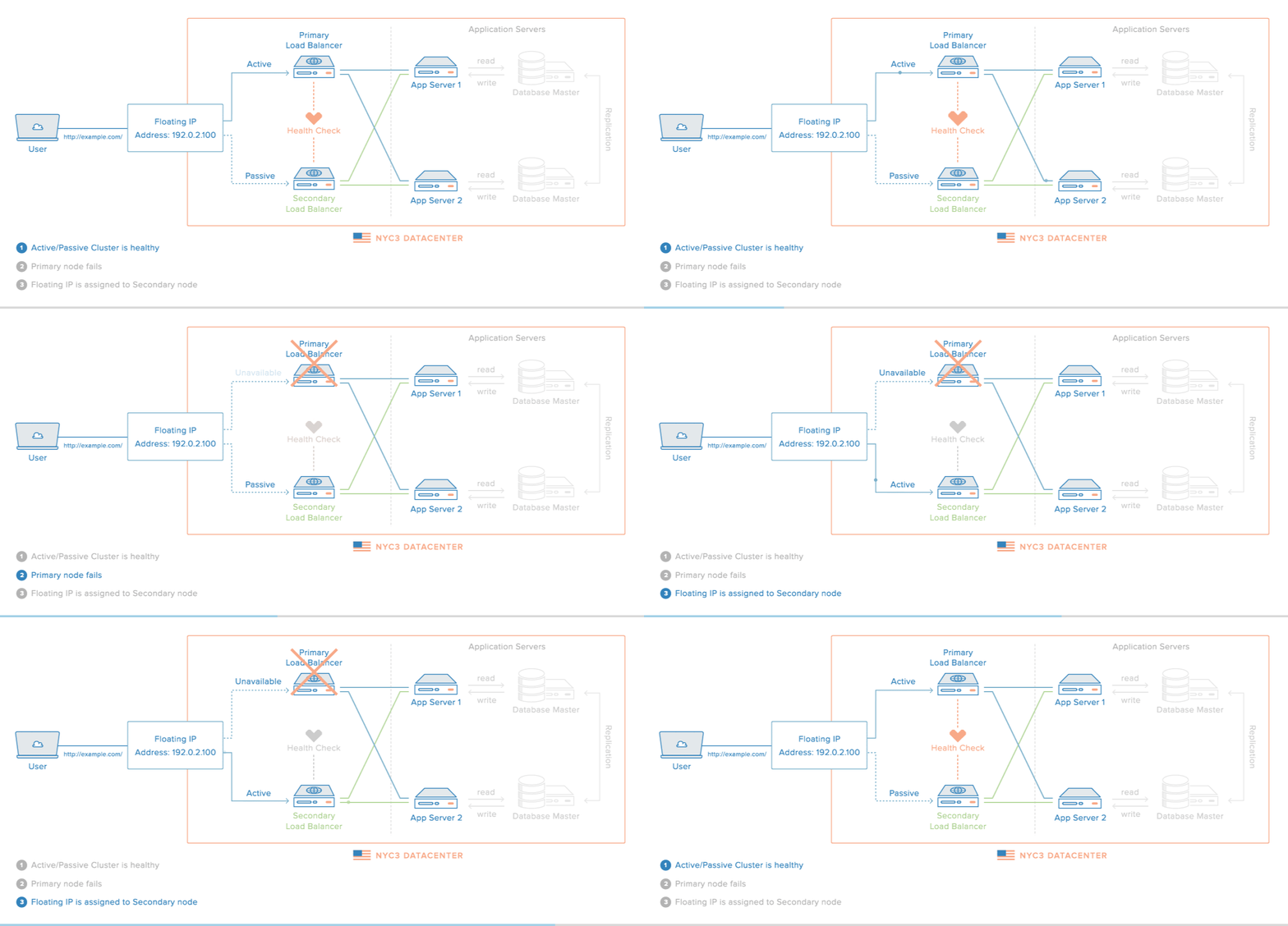
When completed, the HA setup will consist of two Ubuntu 14.04 servers in an active/passive configuration. This will be accomplished by pointing a Floating IP, which is how your users will access your services or website, to point to the primary, or active, server unless a failure is detected. In the event that the Heartbeat service detects that the primary server is unavailable, the secondary server will automatically run a script to reassign the Floating IP to itself via the DigitalOcean API. Thus, subsequent network traffic to the Floating IP will be directed to your secondary server, which will act as the active server until the primary server becomes available again (at which point, the primary server will reassign the Floating IP to itself).
Active/passive Diagram
Note: This tutorial only covers setting up active/passive high availability at the gateway level. That is, it includes the Floating IP, and the load balancer servers—Primary and Secondary. Furthermore, for demonstration purposes, instead of configuring reverse-proxy load balancers on each server, we will simply configure them to respond with their respective hostname and public IP address.
To achieve this goal, we will follow these steps:
  • Create 2 Droplets that will receive traffic
  • Create Floating IP and assign it to one of the Droplets
  • Create DNS A record that points to Floating IP (optional)
  • Install Heartbeat on Droplets
  • Configure Heartbeat to Run Floating IP Reassignment Service
  • Create Floating IP Reassignment Service
  • Test failover

Prerequisites

In order to automate the Floating IP reassignment, we must use the DigitalOcean API. This means that you need to generate a Personal Access Token (PAT), which is an API token that can be used to authenticate to your DigitalOcean account, with read and write access by following the How To Generate a Personal Access Token section of the API tutorial. Your PAT will be used in a script that will be added to both servers in your cluster, so be sure to keep it somewhere safe—as it allows full access to your DigitalOcean account—for reference.
In addition to the API, this tutorial utilizes the following DigitalOcean features:
Please read the linked tutorials if you want to learn more about them.

Create Droplets

The first step is to create two Ubuntu Droplets in the same datacenter, which will act as the primary and secondary servers described above. In our example setup, we will name them "primary" and "secondary" for easy reference. We will install Nginx on both Droplets and replace their index pages with information that uniquely identifies them. This will allow us a simple way to demonstrate that the HA setup is working. For a real setup, your servers should run the web server or load balancer of your choice.
Create two Ubuntu 14.04 Droplets, primary and secondary, with this bash script as the user data:
Example User Data
#!/bin/bash

apt-get -y update
apt-get -y install nginx
export HOSTNAME=$(curl -s http://169.254.169.254/metadata/v1/hostname)
export PUBLIC_IPV4=$(curl -s http://169.254.169.254/metadata/v1/interfaces/public/0/ipv4/address)
echo Droplet: $HOSTNAME, IP Address: $PUBLIC_IPV4 > /usr/share/nginx/html/index.html
This will install Nginx and replace the contents of index.html with the droplet's hostname and IP address (by referencing the Metadata service). Accessing either Droplet via its public IP address will show a basic webpage with the Droplet hostname and IP address, which will be useful for testing which Droplet the Floating IP is pointing to at any given moment.

Create a Floating IP

In the DigitalOcean Control Panel, click Networking, in the top menu, then Floating IPs in the side menu.
No Floating IPs
Assign a Floating IP to your primary Droplet, then click the Assign Floating IP button.
After the Floating IP has been assigned, check that you can reach the Droplet that it was assigned to by visiting it in a web browser.
http://your_floating_ip
You should see the index page of your primary Droplet.

Configure DNS (Optional)

If you want to be able to access your HA setup via a domain name, go ahead and create an A record in your DNS that points your domain to your Floating IP address. If your domain is using DigitalOcean's nameservers, follow step three of the How To Set Up a Host Name with DigitalOcean tutorial. Once that propagates, you may access your active server via the domain name.
The example domain name we'll use is example.com. If you don't have a domain name right now, you should use the Floating IP address instead.

Install Heartbeat

The next step is to install Heartbeat on both servers. The simplest way to install Heartbeat is to use apt-get:
sudo apt-get update
sudo apt-get install heartbeat
Heartbeat is now installed but it needs to be configured before it will do anything.

Configure Heartbeat

In order to get our desired cluster up and running, we must set up these Heartbeat configuration files in /etc/ha.d, identically on both servers:
  1. ha.cf: Global configuration of the Heartbeat cluster, including its member nodes
  2. authkeys: Contains a security key that provides nodes a way to authenticate to the cluster
  3. haresources: Specifies the services that are managed by the cluster and the node that is the preferred owner of the services. Note that this file is not used in a setup that uses a CRM like Pacemaker
We will also need to provide a script that will perform the Floating IP reassignment in the event that the primary Droplet's availability changes.

Gather Node Information

Before configuring ha.cf, we should look up the names of each node. Heartbeat requires that each node name matches their respective uname -n output.
On both servers, run this command to look up the appropriate node names:
  • uname -n
Note the output of the command. The example node names are "primary" and "secondary", which matches what we named the Droplets.
We will also need to look up the network interface and IP address that each node will use to communicate with the rest of the cluster, to determine which nodes are available. You may use any network interface, as long as each node can reach the other nodes in the cluster. We'll use the public interface of our Droplets, which happens to be eth0.
On both servers, use this command to look up the IP address of the eth0 interface (or look it up in the DigitalOcean Control Panel):
  • ip addr show eth0
ip addr show eth0 output:
2: eth0: <BROADCAST,MULTICAST,UP,LOWER_UP> mtu 1500 qdisc pfifo_fast state UP group default qlen 1000 link/ether 04:01:76:a5:45:01 brd ff:ff:ff:ff:ff:ff inet 104.236.6.11/18 brd 104.236.63.255 scope global eth0 valid_lft forever preferred_lft forever inet 10.17.0.28/16 scope global eth0 valid_lft forever preferred_lft forever inet6 fe80::601:76ff:fea5:4501/64 scope link valid_lft forever preferred_lft forever
Note the IP address of the network interface (highlighted in the example). Be sure to get the IP addresses of both servers.

Create ha.cf File

On both servers, open /etc/ha.d/ha.cf in your favorite editor. We'll use vi:
  • sudo vi /etc/ha.d/ha.cf
The file should be new and empty. We need to add the network interfaces and names of each node in our cluster.
Copy and paste this configuration into the file, then replace the respective node names and IP addresses with the values that we looked up earlier. In this example, primary's IP address is 104.236.6.11 and secondary's IP address is 104.236.6.22:
node primary
ucast eth0 104.236.6.11
node secondary
ucast eth0 104.236.6.22
Save and exit. Next, we'll set up the cluster's authorization key.

Create authkeys File

The authorization key is used to allow cluster members to join a cluster. We can simply generate a random key for this purpose.
On the primary node, run these commands to generate a suitable authorization key in an environment variable named AUTH_KEY:
if [ -z "${AUTH_KEY}" ]; then
  export AUTH_KEY="$(command dd if='/dev/urandom' bs=512 count=1 2>'/dev/null' \
      | command openssl sha1 \
      | command cut --delimiter=' ' --fields=2)"
fi
Then write the /etc/ha.d/authkeys file with these commands:
sudo bash -c "{
  echo auth1
  echo 1 sha1 $AUTH_KEY
} > /etc/ha.d/authkeys"
Check the contents of the authkeys file like this:
  • sudo cat /etc/ha.d/authkeys
It should like something like this (with a different authorization key):
/etc/ha.d/authkeys example:
auth1 1 sha1 d1e6557e2fcb30ff8d4d3ae65b50345fa46a2faa
Ensure that the file is only readable by root:
  • sudo chmod 600 /etc/ha.d/authkeys
Now copy the /etc/ha.d/authkeys file from your primary node to your secondary node. You can do this manually, or with scp.
On the secondary server, be sure to set the permissions of the authkeys file:
  • sudo chmod 600 /etc/ha.d/authkeys
Both servers should have an identical /etc/ha.d/authkeys file.

Create haresources File

The haresources file specifies preferred hosts paired with services that the cluster manages. The preferred host is the node that should run the associated service(s) if the node is available. If the preferred host is not available, i.e. it is not reachable by the cluster, one of the other nodes will take over. In other words, the secondary server will take over if the primary server goes down.
On both servers, open the haresources file in your favorite editor. We'll use vi:
  • sudo vi /etc/ha.d/haresources
Now add this line to the file, substituting in your primary node's name:
/etc/ha.d/haresources
primary
Save and exit. This configures the primary server as the preferred host for the floatip service, which is currently undefined. Let's set up the floatip service next.

Create Floating IP Reassignment Service

Our Heartbeat cluster is configured to maintain the floatip service, which a node can use to assign the Floating IP to itself, but we still need to create the service. Before we set up the service itself, however, let's create a script that will assign the Floating IP, via the DigitalOcean API, to the node that runs it. Then we will create the floatip service which will run the Floating IP reassignment script.

Create assign-ip Script

For our example, we'll download a basic Python script that assigns a Floating IP to a given Droplet ID, using the DigitalOcean API.
On both servers, download the assign-ip Python script:
  • sudo curl -L -o /usr/local/bin/assign-ip http://do.co/assign-ip
On both servers, make it executable:
  • sudo chmod +x /usr/local/bin/assign-ip
Use of the assign-ip script requires the following details:
  • Floating IP: The first argument to the script, the Floating IP that is being assigned
  • Droplet ID: The second argument to the script, the Droplet ID that the Floating IP should be assigned to
  • DigitalOcean PAT (API token): Passed in as the environment variable DO_TOKEN, your read/write DigitalOcean PAT
Feel free to review the contents of the script before continuing.
Now we're ready to create the floatip service.

Create floatip Service

To create the floatip service, all we need to do is create an init script that invokes the assign-ip script that we created earlier, and responds to start and stop subcommands. This init script will be responsible for looking up the Droplet ID of the server, via the Droplet Metadata service. Also, it will require the Floating IP that will be reassigned, and the DigitalOcean API token (the Personal Access Token mentioned in the prerequisites section).
On both servers, add open /etc/init.d/floatip in an editor:
  • sudo vi /etc/init.d/floatip
Then copy and paste in this init script, replacing the highlighted parts with your DigitalOcean API key and the Floating IP that should be reassigned:
/etc/init.d/floatip
b7d03a6947b217efb6f3ec3bd3504582
Save and exit.
Make the script executable:
  • sudo chmod u+x /etc/init.d/floatip
When this floatip service is started, it will simply call the assign-ip Python script and assign the specified Floating IP to the Droplet that executed the script. This is the script that will be called by the secondary server, to reassign the Floating IP to itself, if the primary server fails. Likewise, the same script will be used by the primary server, to reclaim the Floating IP, once it rejoins the cluster.

Start Heartbeat

Now that Heartbeat is configured, and all of the scripts it relies on are set up, we're ready to start the Heartbeat cluster!
On both servers, run this command to start Heartbeat:
  • sudo service heartbeat start
You should see output like this:
Heartbeat output:
Starting High-Availability services: Done.
Our HA setup is now complete! Before moving on, let's test that it works as intended.

Test High Availability

It's important to test that a high availability setup works, so let's do that now.
Currently, the Floating IP is assigned to the primary node. Accessing the Floating IP now, via the IP address or by the domain name that is pointing to it, will simply show the index page of the primary server. If you used the example user data script, it will look something like this:
Floating IP is pointing to primary server
Droplet: primary, IP Address: 104.236.6.11
This indicates that the Floating IP is, in fact, assigned to the primary Droplet.
Now, let's open a terminal and use curl to access the Floating IP on a 1 second loop. Use this command to do so, but be sure to replace the URL with your domain or Floating IP address:
example.com
Currently, this will output the same Droplet name and IP address of the primary server. If we cause the primary server to fail, by powering it off or stopping the Heartbeat service, we will see if the Floating IP gets reassigned to the secondary server.
Let's power off the primary server now. Do so via the DigitalOcean Control Panel or by running this command on the primary server:
  • sudo poweroff
After a few moments, the primary server should become unavailable. Pay attention to the output of the curl loop that is running in the terminal. You should notice output that looks like this:
curl loop output:
Droplet: primary, IP Address: 104.236.6.11 ... curl: (7) Failed to connect to example.com port 80: Connection refused Droplet: secondary, IP Address: 104.236.6.22 Droplet: secondary, IP Address: 104.236.6.22 ...
That is, the Floating IP address should be reassigned to point to the IP address of the secondary server. That means that your HA setup is working, as a successful automatic failover has occurred.
You may or may not see the Connection refused error, which can occur if you try and access the Floating IP between the primary server failure and the Floating IP reassignment completion.
Now, you may power on your primary Droplet, via the DigitalOcean Control Panel. Because Heartbeat is configured with the primary Droplet as the preferred host to run the Floating IP reassignment script, the Floating IP will automatically point back to the primary server as soon as it becomes available again.

Conclusion

Congratulations! You now have a basic HA server setup using Heartbeat and a DigitalOcean Floating IP.
If you are looking to create a more robust HA setup, look into using Corosync and Pacemaker or Keepalived.
If you want to extend your Heartbeat setup, the next step is to replace the example Nginx setup with a reverse-proxy load balancer. You can use Nginx or HAProxy for this purpose. Keep in mind that you will want to bind your load balancer to the anchor IP address, so that your users can only access your servers via the Floating IP address (and not via the public IP address of each server).

Source : https://www.digitalocean.com/community/tutorials/how-to-create-a-high-availability-setup-with-heartbeat-and-floating-ips-on-ubuntu-14-04

Silicon Valley Network Administrator

Damn straight. This is what we do. Period. ‪#‎SysAdminDay‬ ‪#‎Funny‬‪#‎Truth‬ ‪#‎IT‬ 

Filter Negative Site by Power DNS And Unbound Ubuntu

Powerdns With Mysql
Powerdns With Mysql

Update Repository
apt-get update

Install Mysql
apt-get install mysql-server mysql-client

pastekan baris code dibawah ini :
CREATE DATABASE powerdns;
GRANT ALL ON powerdns.* TO 'power_admin'@'localhost' IDENTIFIED BY '!tuS@ja';
GRANT ALL ON powerdns.* TO 'power_admin'@'localhost.localdomain' IDENTIFIED BY '!tuS@ja';
FLUSH PRIVILEGES;
USE powerdns;
CREATE TABLE domains (
id INT auto_increment,
name VARCHAR(255) NOT NULL,
master VARCHAR(128) DEFAULT NULL,
last_check INT DEFAULT NULL,
type VARCHAR(6) NOT NULL,
notified_serial INT DEFAULT NULL,
account VARCHAR(40) DEFAULT NULL,
primary key (id)
);
CREATE UNIQUE INDEX name_index ON domains(name);
CREATE TABLE records (
id INT auto_increment,
domain_id INT DEFAULT NULL,
name VARCHAR(255) DEFAULT NULL,
type VARCHAR(6) DEFAULT NULL,
content VARCHAR(255) DEFAULT NULL,
ttl INT DEFAULT NULL,
prio INT DEFAULT NULL,
change_date INT DEFAULT NULL,
primary key(id)
);
CREATE INDEX rec_name_index ON records(name);
CREATE INDEX nametype_index ON records(name,type);
CREATE INDEX domain_id ON records(domain_id);
CREATE TABLE supermasters (
ip VARCHAR(25) NOT NULL,
nameserver VARCHAR(255) NOT NULL,
account VARCHAR(40) DEFAULT NULL
);
quit;

Install Unbound sebagai recursornya
apt-get install unbound
cd /etc/unbound/
wget ftp://ftp.internic.net/domain/named.cache
killall unbound
nano /etc/unbound/unbound.conf

edit config unbound dan sesuaikan agar sesuai dengan kebutuhan. jangan lupa portnya selain 53 dan ipnya ke localhost
#### START UNBOUND CONFIG
server:
verbosity: 1
statistics-interval: 120
num-threads: 4
statistics-cumulative: yes
interface: 127.0.0.1@12345
port: 12345

outgoing-range: 512
num-queries-per-thread: 1024

msg-cache-size: 128m
rrset-cache-size: 256m
so-rcvbuf: 8m

msg-cache-slabs: 8
rrset-cache-slabs: 8
infra-cache-slabs: 8
key-cache-slabs: 8

cache-min-ttl: 600
cache-max-ttl: 86400
infra-host-ttl: 60
infra-lame-ttl: 120

infra-cache-numhosts: 10000
infra-cache-lame-size: 10k

do-ip4: yes
do-ip6: no
do-udp: yes
do-tcp: yes
do-daemonize: yes

access-control: 0.0.0.0/0 allow

chroot: "/etc/unbound"
username: "unbound"
directory: "/etc/unbound"
logfile: ""
use-syslog: no
pidfile: "/etc/unbound/unbound.pid"
root-hints: "/etc/unbound/named.cache"

identity: "DNS"
version: "1.4"
hide-identity: yes
hide-version: yes
harden-glue: yes
use-caps-for-id: yes
harden-dnssec-stripped: yes
do-not-query-address: 127.0.0.1/8
do-not-query-localhost: yes
module-config: "iterator"

#zone localhost
local-zone: "localhost." static
local-data: "localhost. 10800 IN NS localhost."
local-data: "localhost. 10800 IN SOA localhost. nobody.invalid. 1 3600 1200 604800 10800"
local-data: "localhost. 10800 IN A 127.0.0.1"

local-zone: "127.in-addr.arpa." static
local-data: "127.in-addr.arpa. 10800 IN NS localhost."
local-data: "127.in-addr.arpa. 10800 IN SOA localhost. nobody.invalid. 2 3600 1200 604800 10800"
local-data: "1.0.0.127.in-addr.arpa. 10800 IN PTR localhost."

forward-zone:
name: "."
forward-addr: 8.8.8.8
forward-addr: 8.8.4.4

remote-control:
control-enable: yes
control-interface: 127.0.0.1
control-port: 953
server-key-file: "/etc/unbound/unbound_server.key"
server-cert-file: "/etc/unbound/unbound_server.pem"
control-key-file: "/etc/unbound/unbound_control.key"
control-cert-file: "/etc/unbound/unbound_control.pem"
##### END CONFIG

restart powerdns
/etc/init.d/pdns restart

check service powerdns apakah sudah berjalan
ps ax | grep pdns

Test apakah resolve
dig @192.168.0.10 detik.com

Install apache dan php module
apt-get install apache2 libapache2-mod-php5 php5 php5-common php5-curl php5-dev php5-gd php-pear php5-imap php5-mcrypt php5-ming php5-mysql php5-xmlrpc gettext php-db php-mdb2 php-mdb2-driver-mysql
a2enmod rewrite
service apache2 restart

Install phpmyadmin
apt-get install phpmyadmin

download poweradmin untuk menambah atau membuang record dns yang akan di block
wget https://github.com/downloads/poweradmin/poweradmin/poweradmin-2.1.6.tgz
tar xzvf poweradmin-2.1.6.tgz
mv poweradmin-2.1.6 /var/www/poweradmin
touch /var/www/poweradmin/inc/config.inc.php
chown -R www-data:www-data /var/www

Lanjutkan setting poweradmin dengan merujuk ke http://192.168.0.10/poweradmin/install/index.php

isi databasenya dengan merujuk file dari https://docs.google.com/file/d/0BxUNcvINx070eHNMUkROQUFEX1U/edit?pli=1 download lalu masukkan ke mesin linux selanjutnya jalankan perintah dibawah ini
awk '{print "NULL" "\t" $1 "\t" NULL "\t" "NULL" "\t" "NATIVE" "\t" "NULL" "\t" "NULL" }' domain.txt > domains
mysql -u power_admin -p'!tuS@ja' -Dpowerdns -e "LOAD DATA INFILE 'domains' INTO TABLE domains"
mysql -u power_admin -p'!tuS@ja' -Dpowerdns -e "select id,name from domains" > forrecord
awk '{print "NULL" "\t" $1 "\t" $2 "\t" "A" "\t" "1.1.1.1" "\t" "86400" "\t" "0" "\t" "1392620361" "\n" "NULL" "\t" $1 "\t" "*."$2 "\t" "A" "\t" "1.1.1.1" "\t" "86400" "\t" "0" "\t" "1392620361" }' forrecord > records
awk '{print "NULL" "\t" $1 "\t" "1" "\t" "0" "\t" "2" }' forrecord > zones
cp records /var/lib/mysql/powerdns/
cp zones /var/lib/mysql/powerdns/
chmod 666 /var/lib/mysql/powerdns/records
chmod 666 /var/lib/mysql/powerdns/zones
mysql -upower_admin -p'!tuS@ja' -Dpowerdns -e "LOAD DATA INFILE 'records' INTO TABLE records"
mysql -upower_admin -p'!tuS@ja' -Dpowerdns -e "LOAD DATA INFILE 'zones' INTO TABLE zones"

Selesai sudah, filtering domain untuk porno, malware, spyware dan judi telah selesai, semoga bermanfaat bagi rekan rekan sekalian.

Sumber : http://jaringanku.net/2014/03/16/filter-negative-site-by-dns/